Out-of-Order Execution and Superscalar Design
September 8, 202650 min readadvanced
Start with a machine that executes instructions strictly in the order the program wrote them. That is an in-order machine, and it is what CPU Foundations Pipeline and Hazards describes. Give it four…
01.Part 1, the waste that motivates everything
1.1 Four instructions and a stopwatch
Start with a machine that executes instructions strictly in the order the program wrote them. That is an in-order machine, and it is what CPU Foundations Pipeline and Hazards describes. Give it four instructions.
| LDR x1, [x2] ; load from memory, misses L1 and L2, takes 20 cycles | |
| ADD x3, x1, x4 ; needs x1, so it genuinely has to wait | |
| ADD x5, x6, x7 ; needs nothing the load produces | |
| ADD x8, x9, x10 ; needs nothing the load produces |
Count the cycles. The machine issues one instruction per cycle when it can, an ALU add takes one cycle, and the load takes 20 cycles because it went all the way to DRAM.
| Cycle | What happens |
|---|---|
| 0 | LDR issues, memory request goes out, result due at cycle 20 |
| 1 | ADD x3 wants x1. x1 is not there. Stall. |
| 2 to 19 | Still stalled. The pipeline is frozen. |
| 20 | Load data returns |
| 21 | ADD x3 issues |
| 22 | ADD x5 issues |
| 23 | ADD x8 issues |
Four instructions in 24 cycles. That is an IPC, instructions per cycle, of . On a machine physically capable of several instructions per cycle.
Now look at where the waste is. The second instruction had a real reason to wait. It needs the value the load is fetching, and no amount of cleverness conjures that value early. But the third and fourth instructions had no reason at all. Their inputs are x6, x7, x9, and x10, none of which the load touches. They could have executed at cycle 1 and cycle 2. They sat idle for 19 cycles purely because of where they happened to sit in the program text.
That is the entire motivation for this note. An in-order machine stalls on the oldest unready instruction, not on the unready work. Out-of-order execution removes exactly that coupling.
1.2 Now measure what out-of-order actually buys here
Run the same four instructions on a machine that may execute them in any order that respects real data dependences, with two ALU ports.
| Cycle | What happens |
|---|---|
| 0 | All four instructions enter the window. LDR issues. |
| 1 | ADD x5 and ADD x8 both issue. Neither needs the load. |
| 2 to 19 | Nothing left to do. Machine idles. |
| 20 | Load data returns |
| 21 | ADD x3 issues |
Four instructions in 22 cycles. IPC is .
Be honest about that number. It is an improvement of about 9 percent, which is almost nothing, and if you stop here you would conclude that out-of-order execution is not worth the enormous machinery it requires. The reason the gain is small is that there were only two independent instructions available to fill a twenty cycle hole.
1.3 The real lesson, which is about window size
Change one thing. Suppose the program has 40 independent ALU instructions after the load rather than 2.
In order, the machine still stalls 20 cycles on instruction two, then grinds out the remaining 41 instructions one per cycle, for roughly 62 cycles total.
Out of order with a big enough window, the machine issues 2 ALU instructions per cycle starting at cycle 1. It gets through 38 of them in 19 cycles, entirely inside the shadow of the load. The load returns at 20, the dependent add goes at 21, the last couple of adds finish by 22. Roughly 23 cycles.
Sixty-two cycles becomes twenty-three. That is a 2.7x speedup, and it came from the same mechanism as the 9 percent case. The difference is that the machine could see 40 instructions ahead instead of 3.
This gives the governing relationship for the whole design. To keep instructions per cycle flowing across a stall of length cycles, the machine needs to be holding roughly
instructions at once. Work it three times.
| Stall being covered | Latency | Target IPC | In-flight instructions needed |
|---|---|---|---|
| L1 miss, hits in L2 | 14 cycles | 4 | 56 |
| L2 miss, hits in L3 | 40 cycles | 4 | 160 |
| L3 miss, goes to DRAM | 250 cycles | 4 | 1000 |
The first two are buildable. The third is not, and no shipping CPU has a thousand-entry window. This is why prefetching exists, why the memory hierarchy in Cache Organization and Prefetching gets so much attention, and why the honest answer to "why not just make the window bigger" is that the window is fighting a latency that grows faster than the window can.
There is a second thing the window buys on a DRAM miss, and it matters more than instruction overlap. If instruction 5 misses to DRAM and instruction 300 also misses to DRAM, a large window finds the second miss and sends it out while the first is still outstanding, so the two 250-cycle latencies overlap instead of adding. That is memory-level parallelism, and on pointer-free code it is often the dominant benefit of a large window, larger than the ALU overlap.
1.4 The constraint that shapes everything
Before any mechanism, state the rule the machine may not break. The machine may execute in any order it likes. It may not appear to have done so. The program, the debugger, the operating system, and any exception handler must all see a machine that ran strictly in program order. This is the precise exception requirement from CPU Foundations Pipeline and Hazards, and Part 4 shows what goes wrong without it.
So the design splits one notion of order into two. Execution order is whatever is fastest. Commit order, meaning the order in which results become architecturally visible, is strictly program order. Everything below is machinery for maintaining that split.
02.Part 2, names are not values
2.1 Three ways one instruction can depend on another
Two instructions are dependent if swapping them changes the answer. There are exactly three ways this happens, and they are not equally real.
Take a small sequence and label every dependence in it.
| (1) ADD x1, x2, x3 | |
| (2) SUB x4, x1, x5 | |
| (3) ADD x1, x6, x7 |
Read after write, RAW. Instruction 2 reads x1, which instruction 1 wrote. Run 2 first and it reads a stale x1. This is a true dependence. An actual value flows from 1 to 2, and no hardware trick removes it, because you cannot consume a number before it exists.
Write after write, WAW. Instruction 3 writes x1, which instruction 1 also wrote. Run 3 first, then 1, and x1 ends up holding instruction 1's result when it should hold instruction 3's. Wrong answer. But notice no value flowed between them. Instruction 3 does not care what instruction 1 computed. The only thing connecting them is that they picked the same storage location.
Write after read, WAR. Instruction 3 writes x1, which instruction 2 reads. Run 3 first and instruction 2 reads the new x1 instead of the old one. Wrong again, and again no value flowed from 2 to 3.
2.2 Why two of those three are not real
The intuitive reading here is wrong, so slow down. WAW and WAR feel like dependences because breaking them produces wrong answers. They are not dependences between the computations. They are collisions over a name. AArch64 gives the compiler 31 general purpose register names, so any program longer than 31 instructions must reuse them. Instruction 3 above wrote x1 not because it had anything to do with instruction 1, but because the register allocator ran out of names.
Call them what they are. False dependences, also called name dependences.
An in-order machine does not care, because it never reorders anything. An out-of-order machine cares enormously, because false dependences block reordering for a reason that does not exist in the program's data flow. Give instruction 3 a different piece of storage and both the WAW and the WAR vanish.
2.3 Feel the cost concretely
Extend the sequence and draw the dependence graph as it stands.
| (1) ADD x1, x2, x3 | |
| (2) SUB x4, x1, x5 | |
| (3) ADD x1, x6, x7 | |
| (4) ORR x8, x1, x9 | |
| (5) LDR x1, [x10] | |
| (6) EOR x11, x1, x12 |
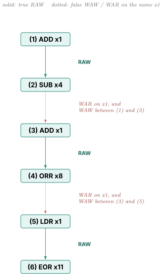
Read the picture. It is one chain of six. Every instruction is downstream of every earlier one, so on any machine, however wide, this sequence takes six cycles. Add ten more ALU ports and it still takes six cycles.
Now read the code again with your eyes and ignore the names. Instructions 1 and 2 form a pair. Instructions 3 and 4 form a pair that reads x6, x7, and x9, none of which 1 or 2 touch. Instructions 5 and 6 form a pair that reads x10 and x12, again untouched. There are three completely independent pairs. On a 3-port machine this should take two cycles, not six.
Six cycles versus two cycles, from nothing but name reuse. That is what renaming is going to recover.
03.Part 3, register renaming
3.1 The idea in one sentence
The program has 31 names. The hardware has hundreds of storage locations. Stop using the program's names as storage addresses.
Concretely, every instruction that writes a register gets a brand new, previously unused physical location for its result, and every instruction that reads a register is pointed at whichever physical location the most recent writer of that name was given. The architectural name becomes a lookup key rather than an address.
Since every write goes somewhere fresh, two writes can never collide, so WAW is structurally impossible. And since a reader was already pointed at the old location before the new write allocated a different one, WAR is structurally impossible too. RAW survives, correctly, because RAW is a real flow of a real value.
3.2 The three structures
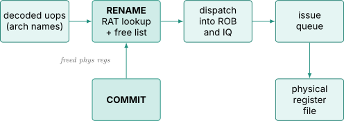
Register alias table, the RAT, sometimes called the rename map or the frontend map. A small array with one entry per architectural register, holding the physical register number currently mapped to it. For AArch64 with 32 architectural entries and 384 physical registers, that is 32 entries of 9 bits each, so 288 bits total. Tiny in storage, brutal in access requirements, because a 6-wide rename stage needs 12 read ports and 6 write ports on those 32 entries in a single cycle.
Free list. A queue of physical register numbers that nobody currently owns. Rename pops from it on every instruction with a destination. Commit pushes onto it when a physical register's last reader is gone.
Physical register file, the PRF. The actual storage, hundreds of entries wide enough for the datapath, with enough read ports to feed every execution unit and enough write ports to absorb every result.
3.3 The rename trace, worked out fully
Start with a map where every architectural register happens to point at the physical register of the same number, so x1 maps to p1, x2 to p2, and so on. The free list holds p40, p41, p42, p43, p44, p45 in that order.
Rename the six instructions from 2.3. For each one, look up the sources in the RAT, pop a fresh physical register for the destination, then write the new mapping into the RAT. The order matters. Look up sources before writing the destination, otherwise an instruction like ADD x1, x1, x2 would read its own new mapping.
| # | Original | Source lookups | Dest popped | Renamed form | RAT after | Old mapping saved for freeing |
|---|---|---|---|---|---|---|
| 1 | ADD x1, x2, x3 | x2 to p2, x3 to p3 | p40 | ADD p40, p2, p3 | x1 to p40 | p1 |
| 2 | SUB x4, x1, x5 | x1 to p40, x5 to p5 | p41 | SUB p41, p40, p5 | x4 to p41 | p4 |
| 3 | ADD x1, x6, x7 | x6 to p6, x7 to p7 | p42 | ADD p42, p6, p7 | x1 to p42 | p40 |
| 4 | ORR x8, x1, x9 | x1 to p42, x9 to p9 | p43 | ORR p43, p42, p9 | x8 to p43 | p8 |
| 5 | LDR x1, [x10] | x10 to p10 | p44 | LDR p44, [p10] | x1 to p44 | p42 |
| 6 | EOR x11, x1, x12 | x1 to p44, x12 to p12 | p45 | EOR p45, p44, p12 | x11 to p45 | p11 |
Now check what happened to each false dependence.
The WAW between 1 and 3 was over the name x1. Instruction 1 writes p40. Instruction 3 writes p42. Different locations, no conflict. They can execute in either order or simultaneously.
The WAR between 2 and 3 was that 2 reads x1 and 3 writes x1. Instruction 2 reads p40. Instruction 3 writes p42. Different locations, no conflict. Instruction 3 may execute before instruction 2 and instruction 2's operand is untouched.
The WAW between 3 and 5, and the WAR between 4 and 5, dissolve the same way.
The RAW edges survive exactly as they should. Instruction 2 reads p40, which instruction 1 writes. Instruction 4 reads p42, which instruction 3 writes. Instruction 6 reads p44, which instruction 5 writes.
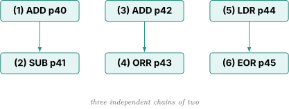
One chain of six became three chains of two. On a machine with three ALU ports and a load port, this sequence now takes two cycles instead of six. Nothing about the program changed. Only the storage assignment did.
3.4 Deriving how many physical registers you need
Work it with small numbers before writing the formula.
Suppose the ISA has 32 architectural registers and the machine allows 8 instructions to be in flight at once, all of which write a register. Count the physical registers that are simultaneously spoken for.
First, the machine must always be able to produce the committed architectural state, meaning the correct current value of all 32 architectural registers as of the last committed instruction. That value lives in some physical register, so 32 physical registers are pinned down at all times just holding the official state.
Second, each of the 8 in-flight instructions has popped a fresh physical register for its own result. Those 8 are separate from the 32, because the old mapping cannot be released until the new instruction commits.
So physical registers are in use, and the machine cannot function with fewer. Generalize.
where is the number of physical registers, is the number of architectural registers, and is the number of in-flight instructions that write to that register file.
Two refinements matter and both are good interview material.
is not the ROB size. It is the number of in-flight instructions writing that specific register file. Stores, branches, and compare-and-branch instructions occupy ROB entries but produce no register result. Floating point and vector instructions consume vector physical registers, not integer ones. So a core with a 600-entry ROB might only need around 350 integer physical registers, because at most a bit over half the window is integer producers at any time. Public die analysis of Apple's Firestorm core reports roughly 350 integer and roughly 380 vector physical registers against a reorder buffer in the 600s, and that ratio is exactly this effect.
Equality is a deadlock, not a design point. If exactly, the free list empties precisely when the window fills, and rename stalls constantly. Real designs carry slack so the free list is rarely empty. When it does empty, rename stalls even though the ROB has room, which is a distinct and separately-reported stall reason in performance counters.
3.5 When does a physical register get freed
This is subtler than it looks and gets asked.
The obvious answer, free a physical register when its last reader has read it, is wrong and unimplementable. The machine does not know how many readers a register will have, because instructions that will read it have not been fetched yet.
The actual rule is this. When instruction commits, the physical register that held the previous mapping of 's architectural destination is freed. Follow it in the trace above. When instruction 3 commits, it frees p40, because p40 was x1's mapping before instruction 3 took over. That is safe because commit is in program order, so every instruction older than 3 has already committed, and any instruction that reads p40 must be older than 3, since anything younger would have been renamed to p42 or later.
There is a second freeing path. When a mispredicted branch is squashed, every physical register allocated by the squashed instructions returns to the free list, and the RAT is rolled back. Part 6 covers how.
3.6 Two ways to store the result
Two classical organizations, and interviewers sometimes probe which one you are describing.
Unified physical register file. One big array holds both speculative results and committed architectural state. Commit is just a pointer update in a retirement map, and nothing is copied. This is what modern designs use.
ROB-as-storage, the P6 style. Results are written into the reorder buffer entry and copied into a separate architectural register file at commit. Simpler to reason about, used by the Intel P6 family, but it needs a physical copy at commit and an extra operand-source mux at read time, since an operand might come from the ARF or from any ROB entry. It fell out of favor for those reasons.
If asked where a result lives before commit, the modern answer is the physical register file, and commit does not move it.
04.Part 4, the reorder buffer, which exists for correctness
4.1 The bug you get without one
Renaming lets instructions execute out of order. Now watch what that breaks if you let results become architecturally visible as soon as they are computed.
| (1) ADD x6, x6, #1 ; one cycle, finishes immediately | |
| (2) LDR x4, [x5] ; takes a page fault, x5 points at an unmapped page | |
| (3) ADD x7, x7, #1 ; one cycle, finishes immediately |
Out of order, instructions 1 and 3 complete in a couple of cycles. Instruction 2 goes to the memory system, walks the page table, discovers the page is not present, and raises a page fault perhaps 30 cycles later.
A page fault is an exception. Control transfers to the operating system. The OS reads the faulting program counter, which points at instruction 2, allocates a page, maps it in, and returns to re-execute instruction 2.
Now count what happened to x7. Instruction 3 already ran once, before the fault was even known about, and incremented x7. After the handler returns and re-executes from instruction 2, instruction 3 runs again and increments x7 a second time. The program's variable is now off by one, silently, with no error reported anywhere.
That is the bug. And note that it is not a corner case. Any instruction after a faulting instruction that has already modified state produces it.
4.2 What precise means
An exception is precise if, at the moment the handler starts, three things hold. Every instruction before the faulting one has fully completed and its results are visible. The faulting instruction itself has had no effect. Every instruction after it has had no effect either, as if it had never been fetched.
That promise is not optional. Demand paging needs it, because the handler must fix the page and restart the exact instruction. Debuggers need it, since a breakpoint must show a coherent machine. Context switching on an interrupt needs it, because the saved state must be resumable.
So the machine must be able to undo everything younger than any given point, at any time, cheaply. Since it cannot undo a write that already landed in architectural state, the answer is to never let a younger write land until every older instruction is known to be safe.
4.3 The structure
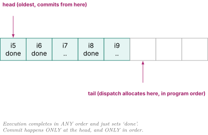
The reorder buffer is a circular FIFO holding one entry per in-flight instruction, in strict program order. Instructions are allocated entries at dispatch, which is right after rename, in program order, at the tail. They are removed at the head, also in program order, when they commit.
An entry holds enough to commit or to squash the instruction.
| Field | Purpose |
|---|---|
| valid / busy | entry is allocated |
| PC | needed for the exception return address |
| destination architectural register | which name this instruction writes |
| destination physical register | where the result was put |
| previous physical mapping | what to free at commit, what to restore on squash |
| done | result has been produced |
| exception status | fault type, if any, discovered during execution |
| instruction type bits | store, branch, serializing, etc. |
Note what is not in the entry on a modern design. The result value is not there. It is in the physical register file, per 3.6.
4.4 The commit trace
Take the ROB above with a 2-wide commit stage and walk it.
| Cycle | Head entry | done? | Action |
|---|---|---|---|
| 1 | i5 | yes | commit i5, free its previous mapping, advance head |
| 1 | i6 | yes | commit i6 in the same cycle, 2-wide commit |
| 2 | i7 | no, still executing | stall commit. i8 is done but cannot pass i7. |
| 3 | i7 | no | still stalled |
| 4 | i7 | yes | commit i7 |
| 4 | i8 | yes | commit i8 |
| 5 | i9 | yes | commit i9 |
Read cycle 2 carefully. Instruction i8 has finished. Its result is sitting in the physical register file, fully computed, and any younger instruction that needs it can already read it. But it may not commit, because i7 is older and unfinished. If i7 turns out to fault, i8 must be undone, and undoing it is only possible while it is uncommitted.
That is the whole trick. Out-of-order execution, in-order commit. The machine is a racecar internally and a metronome at the boundary.
4.5 Why the ROB is a correctness structure
Beginners often say the ROB is what makes out-of-order execution fast. It is the opposite. The ROB is pure overhead against speed. It adds a pipeline stage, it adds a structure that fills up and stalls dispatch, and it holds finished results hostage.
Renaming is what makes the machine fast. The ROB is what makes it legal. If precise exceptions were not required you could delete the ROB and the machine would run at least as fast.
The ROB affects performance only indirectly, because its size sets the window from Part 1.3. That is a side effect of it being the structure that bounds in-flight instructions, not of what it does.
A squash is where it earns its keep. When the head instruction is found to have faulted, the machine sets tail equal to head, restores the retirement map into the frontend RAT, returns every physical register allocated by the squashed instructions to the free list, drains the issue queues and load-store queues, and vectors to the handler. All of that is possible only because nothing younger had been allowed to become architectural.
4.6 What sets ROB size in practice
Part 1.3 says the window should be roughly IPC times the latency you want to hide, which suggests a few hundred entries against an L2 or L3 hit. That is what shipping cores do. Beyond that returns fall off for three reasons, and naming all three is a strong answer.
Available instruction-level parallelism runs out, so doubling from 300 to 600 entries might expose 20 percent more independent work rather than 100 percent more. The ROB is also not the only thing that must grow, since a bigger ROB against the same physical register file just moves the stall to the free list, and the load queue, store queue, and issue queues all have to grow in step while scaling far worse. And the whole thing is bounded by branch prediction. If the machine mispredicts once every 150 instructions, filling a 600-entry window means the tail 450 entries are usually on a wrong path and get thrown away. That is the direct coupling to Front End and Branch Prediction, and it is why a very large window and a very good predictor are not independent design choices.
05.Part 5, the scheduler and the loop that sets your clock frequency
5.1 What an issue queue entry holds
The issue queue, also called a reservation station or scheduler, holds instructions that have been renamed and dispatched but are not yet ready to execute. Each cycle it must find instructions whose operands have become available and send them to execution units.
An entry looks like this.
| Field | Width, roughly | Purpose |
|---|---|---|
| valid | 1 bit | entry occupied |
| opcode / control | ~10 bits | what to do |
| ROB index | ~10 bits | which in-flight instruction this is |
| destination tag | 9 bits | physical register it will write |
| source 1 tag | 9 bits | physical register it reads |
| source 1 ready | 1 bit | is that value available yet |
| source 2 tag | 9 bits | second operand |
| source 2 ready | 1 bit | |
| port eligibility | ~4 bits | which execution units can run this |
| age | ~7 bits | for oldest-first selection |
Around 60 bits per entry. A 60-entry queue is therefore only about 3600 bits of storage, which is nothing. The storage is not the problem. The comparisons are.
5.2 Wakeup is a content-addressable match
When an instruction is about to produce a result in physical register p40, the machine broadcasts the tag p40 across the queue. Every entry compares that tag against both of its source tags. A match sets the corresponding ready bit.
This is exactly a CAM, a content-addressable memory, from Arbiters FIFOs and CAMs. You do not present an address and get data. You present data and every location tells you whether it matches.
Draw it with four entries and one broadcast.
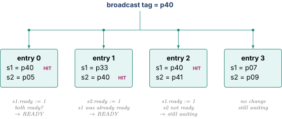
Now count the hardware. Each comparison is 9 bits wide. Each entry has 2 sources. And a wide machine finishes several instructions per cycle, so several tags broadcast at once. For a 60-entry queue with 2 sources and 6 result buses,
Every one of those comparators toggles, and the 6 broadcast wires each have to reach 120 comparator inputs spread across the physical extent of the queue. That fanout and that wire length is the delay, and it is also why the scheduler is one of the hottest blocks in the core by power density. This is the first place where Power Fundamentals and Clock Gating becomes directly relevant, because gating the broadcast when no result is produced on a given bus is a real and worthwhile optimization.
5.3 Select is a priority encoder
After wakeup, some set of entries are fully ready. There may be 20 of them and only 4 execution ports. Select picks which ones go.
The usual policy is oldest first, because the oldest ready instruction is statistically the one most other instructions are waiting on, and because oldest-first prevents starvation. Implementing it is a priority encoder over the ready bits, ordered by age.
Picking one out of 60 is a priority encoder. Picking four out of 60 for four different ports, where instructions have port eligibility restrictions, is considerably worse. You cannot just cascade four priority encoders naively, because each one has to mask off what the previous ones took, and that masking is serial. Real designs partition the queue into per-port or per-group subqueues to break the problem into smaller pieces, which is one of the main reasons distributed schedulers exist.
5.4 The loop, and why it must fit in one cycle
Here is the part that matters most for an RTL role.
Consider two dependent single-cycle instructions, an ADD producing p40 and a SUB consuming p40. For the machine to lose nothing, the SUB must execute in the cycle immediately after the ADD executes. That is called back-to-back dependent execution, and it is not a luxury. Dependent chains are everywhere in real code.
Work out what must happen for that to be true. Assume select in cycle means execute in cycle .
| Cycle | ADD (producer) | SUB (consumer) |
|---|---|---|
| selected. Broadcasts p40 now, before executing, on the promise that it takes 1 cycle. | CAM compare on p40 hits, ready bit sets, participates in select this same cycle | |
| executes | executes | |
| result written back | result written back |
Look at what happened inside cycle . The ADD was selected. Its destination tag was driven onto a broadcast bus that spans the queue. Sixty entries compared it. Ready bits were computed. The AND of the two ready bits per entry was computed. A priority encoder ran over all 60 results and picked winners. And the winner's tag then has to be driven onto the broadcast bus for the next cycle.
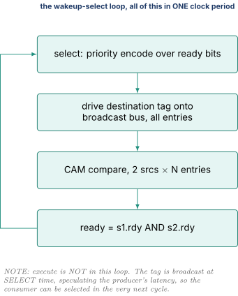
This loop cannot be pipelined. Not "is hard to pipeline." Cannot, without changing the machine's behavior.
Suppose you split it into two cycles, wakeup in one and select in the next, to relax timing. Then the SUB cannot be selected in cycle . It gets selected in cycle and executes in . There is now a one cycle bubble between every dependent pair.
Quantify that. A dependent chain of 10 single-cycle instructions took 10 cycles. Now it takes 20. On code that is mostly dependent chains, which is most scalar integer code, IPC roughly halves. You gave up half the machine's performance to relax one timing path. Nobody makes that trade.
So this loop is a genuine, hard, single-cycle path, and it is one of the two or three paths that actually set the clock frequency of a high-performance core, alongside the L1 cache access and the bypass network.
5.5 Why issue queues are tens of entries and ROBs are hundreds
This is the question the section above was built to answer, and it is a very good one to be asked.
The ROB and the issue queue both hold in-flight instructions, so a naive reading suggests they should be the same size. They differ by an order of magnitude, roughly 60 entries against roughly 600. The reason is entirely about whether the structure sits on a loop.
| Reorder buffer | Issue queue | |
|---|---|---|
| Access pattern | FIFO, allocate at tail, commit at head | associative match against all entries |
| Circuit | ordinary SRAM plus two pointers | CAM plus priority encoder |
| Delay growth with size | almost flat, it is a RAM | grows with entries, from broadcast wire length, comparator load, and encoder fan-in |
| On a single-cycle feedback loop? | no | yes |
| Can its access be pipelined? | yes, allocate and commit can each take several cycles | no, see 5.4 |
| Cost of doubling it | more area and leakage | less frequency for the entire chip |
That last row is the answer in one line. Doubling the ROB costs area. Doubling the issue queue costs clock frequency across the whole core. Since frequency multiplies every instruction while window size only helps the fraction of code that is latency-bound, the trade lands very asymmetrically.
The design responses to this are worth naming. Split the one big queue into several small distributed queues, one per port cluster, so each CAM is small and its broadcast wires are short. Restrict how many result buses broadcast into each queue. Bank the queue by age so the priority encoder only looks at the oldest region most cycles.
5.6 Data-capture versus non-data-capture
A data-capture scheduler, which is what Tomasulo's original reservation stations in Tomasulo's Algorithm did, stores the operand values inside the queue entry. When a result is broadcast, the tag and the 64-bit value both go out and matching entries latch the value. The register file is read once at dispatch and never again. The cost is that each entry now holds 128 bits of data instead of 20 bits of tags, so the queue is six times bigger and the broadcast buses carry 64 bits instead of 9.
A non-data-capture scheduler stores only tags, and the instruction reads the physical register file after select on its way to the execution unit. Tiny entries, narrow broadcast buses, at the price of enough register file read ports for every issue slot plus a register-read pipeline stage. Every modern design does this, and the port pressure it creates is exactly the problem in 7.3.
5.7 Speculative wakeup for variable-latency producers
Section 5.4 said the producer broadcasts its tag at select time, before executing, on the promise that it takes a known number of cycles. For an ADD that promise is safe. For a load it is not.
The scheduler assumes an L1 hit of say 4 cycles and broadcasts the load's tag far enough ahead that dependents select at exactly the right moment and the data arrives just in time on the bypass network. If the load hits, dependent instructions run with zero bubbles. If the load misses, the dependents have already been selected, have already read their other operands, and are sitting in execution units expecting data that is not coming. That is replay, and it is Part 6.4.
06.Part 6, speculation and recovery
6.1 Everything the machine is guessing about
Modern cores speculate on far more than branch direction, and each guess needs its own recovery path. Branch direction and branch target, per Front End and Branch Prediction. Load latency, per 5.7. Memory dependence, meaning whether a load overlaps an earlier store whose address is not yet computed, per Load Store and Memory Ordering. Way prediction in the cache, per Cache Organization and Prefetching.
6.2 Recovery by walking the ROB
The simplest correct mechanism. When a branch is found to be mispredicted, do nothing until it reaches the head of the ROB. At that point every older instruction has committed and the retirement map holds the correct architectural mapping, so copy that map into the frontend RAT, flush everything, and restart fetch at the correct target.
Correct, simple, and slow, in two separate ways.
Waiting for the head. If the mispredicted branch is 200 entries deep and the oldest instruction is a load that missed to DRAM, the branch waits 250 cycles before recovery even begins, while the machine burns power executing a wrong path.
The walk itself. A variant recovers earlier by walking backward from the tail to the branch, undoing each rename by restoring the saved previous mapping from each ROB entry. At 4 entries undone per cycle with 300 younger instructions, that is 75 cycles of walking. On a machine whose branch penalty budget is 15 cycles, 75 cycles is catastrophic.
6.3 Recovery by checkpoint
The fast mechanism. At each branch, save a complete copy of the RAT. On a misprediction, restore that copy in a single cycle.
Size it. The RAT is 32 entries of 9 bits, so 288 bits. A checkpoint is a 288-bit shadow copy. Sixteen checkpoints cost bits, plus a 16-to-1 mux tree 288 bits wide to restore from any of them, plus the logic to allocate and free checkpoint slots.
That is a real cost but not a prohibitive one, and it turns a 75-cycle recovery into a 1-cycle recovery. The catch is that you have a fixed number of checkpoints and branches are dense. If code has a branch every 6 instructions and the window is 600 instructions, there are 100 branches in flight and only 16 checkpoints. When checkpoints run out, either dispatch stalls or the machine falls back on walking.
The practical resolution is selective checkpointing. Modern predictors produce a confidence signal alongside the prediction, per Front End and Branch Prediction. Checkpoint only the low-confidence branches, since those are the ones likely to need recovery, and let the high-confidence ones fall back to a ROB walk on the rare occasions they are wrong.
| ROB walk | Checkpoint | |
|---|---|---|
| Storage cost | none beyond the ROB fields already present | one RAT copy per checkpoint |
| Recovery latency | tens of cycles, or hundreds if waiting for the head | 1 cycle |
| Scales with branch density | yes, always available | no, fixed number of slots |
| Typical use | fallback and for exceptions | low-confidence branches |
Note that exceptions almost always use the walk or the retirement map, never a checkpoint. Exceptions are rare enough that recovery latency does not matter, and a checkpoint per instruction would be absurd.
6.4 Replay
Return to the load latency guess from 5.7. Draw the failure.
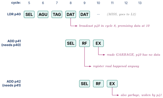
The load's dependents were woken on a promise that was broken. Both the direct consumer and its own consumers are now polluted. They must be squashed and re-executed once the data actually arrives. That re-execution is replay.
Replay is much cheaper than a full pipeline flush, which is the point. You do not throw away the whole window, only the instructions in the load's dependence shadow that issued too early. But it requires keeping those instructions in the issue queue rather than deallocating them at select, which increases queue occupancy, and it requires tracking which instructions were woken speculatively.
6.5 Replay storms
Now the failure mode that makes this hard microarchitecture rather than a bookkeeping detail.
Consider a load that keeps failing for a reason that does not resolve quickly. A bank conflict in the L1, a store-to-load forwarding attempt that cannot be satisfied because the store's data is not ready, a TLB miss in progress, or an L2 access that keeps getting retried. Each time the load is replayed, it re-broadcasts its tag, which re-wakes its dependents, which issue, which fail again, which get replayed again.
Each round of that consumes issue slots, register file read ports, and execution unit cycles, all producing nothing. Meanwhile the instructions cycling in the loop are older than most of the window, so oldest-first select prioritizes them, and they crowd out useful work. The machine can enter a state where throughput collapses to near zero while power consumption stays at maximum. That is a replay storm, and it has shipped in real products.
The mitigations are worth naming because they show you understand it as an engineering problem.
Cap the number of replays per instruction, after which the instruction is re-issued non-speculatively, meaning it waits for the load data to be definitively present rather than being woken on a promise. Add a load hit predictor that learns which loads tend to miss and refuses to wake their dependents speculatively, trading a bubble on those loads for never storming. Hold speculatively-woken instructions in a separate small replay queue rather than leaving them in the main scheduler, so a storm cannot monopolize the scheduler. Detect lack of forward progress at the commit head and force a full flush and in-order restart as a last resort, which is slow but guarantees the machine escapes.
07.Part 7, width, and every structure that fights it
7.1 The rule about widening
Widening a machine only helps if every stage widens together. A machine that fetches 8, decodes 8, renames 8, but issues 4 is a 4-wide machine that burns extra front-end power. That sounds obvious, and it is exactly why wide machines are hard, because three of the structures involved are quadratic in width.
7.2 The bypass network
Bypass, also called forwarding, is the wiring that lets a result go directly from the output of one execution unit to the input of another without a round trip through the register file. It is what makes back-to-back dependent execution possible at all.
Count the wires. With execution units, each has 1 result output and 2 operand inputs. Every operand input must be able to select from any of the results, plus the register file. So each of the operand inputs needs an -input multiplexer, and each of those muxes is 64 bits wide.
Work three widths.
| Execution units | Mux inputs | 64-bit wires crossing the datapath |
|---|---|---|
| 2 | 12 | 768 |
| 4 | 40 | 2560 |
| 8 | 144 | 9216 |
Doubling from 4 to 8 units did not double the bypass network. It nearly quadrupled it. And these are not short wires. They run the full physical width of the execution cluster, so their delay is wire-dominated in the sense of Digital Logic and Timing section 1.2, meaning it does not improve much with process scaling.
The bypass network is frequently the critical path in the execution cluster, competing with the wakeup-select loop for that honor.
7.3 Register file ports
Each in-flight instruction reads up to 2 operands and writes 1 result. An -wide machine therefore needs roughly read ports and write ports on the physical register file.
The problem is how SRAM cell area scales with ports. Each additional port needs its own wordline running horizontally through every cell in the row and its own bitline pair running vertically through every cell in the column. The cell becomes wire-limited, and its area grows roughly as the square of the port count.
| Width | Read ports | Write ports | Total | Relative cell area, |
|---|---|---|---|---|
| 2 | 4 | 2 | 6 | 1.0x |
| 4 | 8 | 4 | 12 | 4.0x |
| 8 | 16 | 8 | 24 | 16x |
Sixteen times the area for four times the width, and access time grows too because the bitlines are longer and more heavily loaded. Since the register file read is inside the execute pipeline, that access time is directly on the critical path.
The standard responses are banking, splitting the file into banks with fewer ports each and accepting occasional bank conflicts, and clustering, per 7.6.
7.4 Rename group dependency checking
The subtle one, and a good discriminator in an interview.
Rename processes a group of instructions in the same cycle. Suppose the group is
| ADD x1, x2, x3 | |
| SUB x4, x1, x5 <-- reads x1, which the instruction above just wrote |
The RAT read for SUB's source x1 returns the old mapping, because the RAT write from ADD has not happened yet. They are in the same cycle. So rename must detect, within the group, that SUB's source matches an older instruction's destination, and bypass the newly-allocated physical register instead of the RAT output.
Count the comparisons. Instruction in the group must compare each of its 2 sources against the destinations of all older instructions in the group.
| Rename width | Comparisons | Also needed |
|---|---|---|
| 2 | 2 | 2-to-1 mux per source |
| 4 | 12 | pick the youngest matching producer, so a priority mux |
| 8 | 56 | 8-way priority mux per source, on a tight path |
And the muxing is not simple, because if two older instructions in the group both wrote x1, the correct source is the younger of them. So each source needs a priority mux over all older group members, resolved in the same cycle as the RAT read. This is why rename is often the stage that gets split across two pipeline cycles in very wide designs, at the cost of one more cycle of branch misprediction penalty.
7.5 Move elimination and zero idioms
Now the techniques that buy width back, which all share one theme. Do the work somewhere cheaper than the execution units.
Move elimination. A register-to-register move, MOV x5, x3, copies a value. It occupies a rename slot, an issue queue entry, an execution port, a register file write, and a physical register, all to move a number that already exists.
Instead, handle it entirely in rename. Look up x3's mapping, and point x5 at the same physical register. No new physical register, no issue queue entry, no execution.
| Step | Without elimination | With elimination |
|---|---|---|
| Physical register allocated | yes, a fresh one | no |
| Issue queue entry | yes | no |
| Execution port cycle | yes | no |
| Cycles of latency | 1 | 0 |
| RAT update | x5 to new p | x5 to the same p as x3 |
The complication is freeing. Two architectural names now point at one physical register, so the commit-time freeing rule from 3.5 would free it too early. The fix is a reference count per physical register, incremented on each extra mapping and decremented at commit, with the register returning to the free list only when the count reaches zero. That reference counting logic is the real cost of move elimination and it is a nontrivial piece of RTL.
Zero idiom elimination is the same trick for a different pattern. EOR x1, x1, x1 and SUB x1, x1, x1 both produce zero regardless of what x1 held, and compilers emit them constantly to zero a register. The renamer recognizes the pattern, points x1 at a dedicated physical zero register, and never issues the instruction. On x86 the XOR eax, eax idiom is so common that eliminating it is worth several percent, and the crucial subtlety is that the renamer must recognize it without reading x1, which means it must know the instruction produces zero from the encoding alone rather than from the data.
7.6 Fusion
Macro-op fusion combines two architectural instructions into one internal operation at decode. The canonical case is a compare followed immediately by a conditional branch, which appears in essentially every loop and every if.
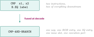
Two instructions become one everywhere downstream. The ROB holds one entry instead of two, so the effective window grows. The rename group carries one instruction instead of two, so the effective width grows. Every quadratic cost in this Part gets a smaller or to square.
Micro-op fusion goes the other direction. A complex operation that must eventually split into several micro-ops is kept as a single entry through rename, dispatch, and the ROB, and split only at issue into the operations that go to different ports. An x86 memory-operand ALU instruction like ADD [mem], eax is the standard example, needing a load, an add, and a store, but occupying one ROB entry.
Same economics both ways. The structures that are expensive to widen see fewer things, and the cheap structures at the back do the extra work.
7.7 Clustering
The last technique, and the one that directly attacks 7.2 and 7.3. Split the execution engine into two or more clusters, each with its own bank of the register file, its own bypass network, and its own subset of the issue queue. Bypass within a cluster is fast at one cycle. Bypass between clusters costs two or three.
Recount the bypass network from 7.2 with two clusters of 4 units instead of one cluster of 8.
| Organization | Intra-cluster bypass mux inputs | Total |
|---|---|---|
| One 8-wide cluster | 144 | |
| Two 4-wide clusters | each | 80, plus a narrow inter-cluster path |
Eighty instead of 144, and the wires are physically half as long because each cluster occupies half the area. The cost is that any dependence crossing a cluster boundary pays an extra cycle or two, so IPC drops a few percent, and the scheduler now needs a steering policy deciding which cluster each instruction goes to. Steering badly is worse than not clustering at all, since a bad policy sends every dependent pair across the boundary.
This is a pure frequency-versus-IPC trade, and which way it lands depends on the design philosophy. A design targeting very high clock frequency clusters aggressively. A design targeting very high IPC at moderate frequency, which is the publicly-reported Apple philosophy of wide and low-clocked, has less reason to.
08.Part 8, the whole machine, traced
8.1 The pipeline
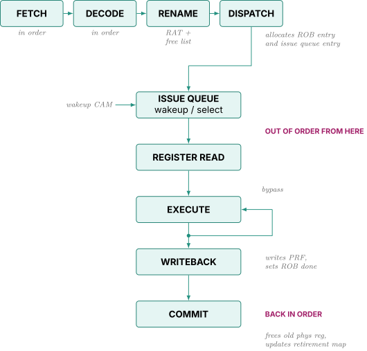
Everything from fetch to dispatch is in program order. Everything from issue to writeback is out of order. Commit is back in program order. Two order-restoring boundaries, and the ROB is the thing that spans them.
8.2 A five-instruction cycle-by-cycle trace
Take a 2-wide machine with a 4-cycle L1 load, two ALU ports, one load port, one store port, and 2-wide commit.
| i1: LDR x1, [x2] ; hits L1, 4 cycles | |
| i2: ADD x3, x1, x4 ; depends on i1 | |
| i3: ADD x5, x6, x7 ; independent | |
| i4: SUB x8, x5, x9 ; depends on i3 | |
| i5: STR x3, [x10] ; depends on i2 |
| Cycle | Fetch | Decode | Rename | Dispatch | Select | Execute | Writeback | Commit |
|---|---|---|---|---|---|---|---|---|
| 1 | i1 i2 | |||||||
| 2 | i3 i4 | i1 i2 | ||||||
| 3 | i5 | i3 i4 | i1 i2 | |||||
| 4 | i5 | i3 i4 | i1 i2 | |||||
| 5 | i5 | i3 i4 | i1 | |||||
| 6 | i5 | i3 | i1 (1 of 4) | |||||
| 7 | i4 | i1 (2), i3 | ||||||
| 8 | i1 (3), i4 | i3 | ||||||
| 9 | i2 | i1 (4) | i4 | |||||
| 10 | i5 | i2 | i1 | |||||
| 11 | i5 (addr) | i2 | i1 | |||||
| 12 | i5 | i2 i3 | ||||||
| 13 | i4 i5 |
Read the interesting rows.
Cycle 5. i1 is selected. i2 is sitting in the queue with its ready bit clear, because p40 has not been broadcast. i3 and i4 have not been dispatched yet.
Cycle 6 and 7. i3 and i4 are selected and execute while i1 is still in the middle of its load. This is the entire point of the machine. Program-order instructions 3 and 4 ran before program-order instruction 2.
Cycle 8. i1 broadcasts its destination tag, three cycles into a four-cycle load, speculating the hit. This is the speculative wakeup from 5.7. If the load were to miss, i2 would have to be replayed.
Cycle 8. i3 writes back. Its result is done and available. But look at the commit column. Nothing commits until cycle 11.
Cycle 11. i1 commits, because it is now at the ROB head and done. i3 has been finished for three cycles and still waits, because i2 is older and not yet written back.
Cycles 12 and 13. Commit catches up two per cycle.
The gap between cycle 8, when i3 finished, and cycle 12, when i3 committed, is the ROB doing its job. Four cycles during which i3's result existed and was usable by younger instructions but was not architecturally real, and could have been thrown away instantly if i1 or i2 had faulted.
09.Part 10, check yourself
Answer out loud, in full sentences, as if an interviewer asked. If you cannot, reread the section named.
- Give a four-instruction sequence where out-of-order execution helps, count the cycles both ways, and then explain why the gain on that specific sequence is disappointing. (1.1, 1.2)
- How large a window would you need to fully hide a 250-cycle DRAM miss at IPC 4, and what does the answer tell you about why prefetching exists? (1.3)
- Name the three dependence types. Which two are not real dependences, and what exactly are they conflicts over? (2.1, 2.2)
- Walk the six-instruction rename table and point at where the WAW and the WAR disappeared. Why does the RAW survive? (3.3)
- Derive from scratch with 32 architectural registers and 8 in-flight instructions. Then explain why a 600-entry ROB does not imply 632 integer physical registers. (3.4)
- When is a physical register returned to the free list, and why is "when its last reader has read it" not implementable? (3.5)
- Construct a three-instruction sequence where allowing out-of-order writes to architectural state produces a silently wrong answer after a page fault. (4.1)
- Is the reorder buffer a performance structure or a correctness structure? Defend the answer. (4.5)
- Draw the wakeup-select loop. Name every step inside the single clock period, and explain why execute is not one of them. (5.4)
- A colleague proposes pipelining wakeup and select over two cycles to close timing. Quantify what that costs on a ten-instruction dependent chain. (5.4)
- Issue queues are roughly 60 entries and ROBs are roughly 600. Explain the order of magnitude in terms of which structure sits on a feedback loop. (5.5)
- Compare checkpoint recovery against ROB-walk recovery on storage cost and recovery latency, and explain why real designs use both. (6.2, 6.3)
- What is a replay storm, what triggers one, and name two mitigations? (6.4, 6.5)
- Why does doubling issue width roughly quadruple the bypass network and roughly quadruple the register file cell area? Show the counting. (7.2, 7.3)
- In the cycle trace, i3 writes back at cycle 8 and commits at cycle 12. What is happening in between, and what would have happened if i1 had faulted at cycle 10? (8.2)
10.Part 11, related notes
- Front End and Branch Prediction for what feeds this machine, and for why window size and predictor accuracy are not independent design choices
- CPU Foundations Pipeline and Hazards for the hazard taxonomy and precise exceptions this note assumes throughout
- Load Store and Memory Ordering for memory dependence speculation, the other big speculation the machine does
- Cache Organization and Prefetching for why the window cannot cover DRAM and what covers it instead
- Arbiters FIFOs and CAMs for the CAM and priority encoder circuits the scheduler is literally built from
- Digital Logic and Timing for why the wakeup-select loop being a single-cycle path is the whole story
- Register Renaming and The Reorder Buffer (ROB) for the vault's deeper treatment
- Issue Queues and Schedulers for scheduler variants beyond what is here
- Lab: gem5 Out-of-Order Modeling to actually build one, which is the thing that closes the gap in Part 9