Anatomy of an Instruction Set
September 8, 202659 min readintermediate
Every program that runs on a processor communicates through a precisely defined contract. The contract specifies which instructions exist, how they are encoded in binary, which registers they can name, what…
Every program that runs on a processor communicates through a precisely defined contract. The contract specifies which instructions exist, how they are encoded in binary, which registers they can name, what happens when something goes wrong, and in what order stores become visible to other cores. This contract is the instruction set architecture, or ISA. It is the single most stable layer of the computing stack introduced in Chapter 1. The x86 ISA has survived since 1978. The ARM A32 encoding has survived since 1985. Programs compiled against those encodings still run on hardware built decades later. The ISA persists because the cost of breaking it exceeds the cost of carrying its legacy forward.
This chapter takes the ISA apart. It examines each element of the contract in turn: the instruction format that encodes an operation into a fixed or variable number of bits, the register file that supplies operands, the addressing modes that compute memory addresses, the exception model that handles faults and interrupts, the memory ordering model that governs multicore visibility, and the calling conventions that let independently compiled functions cooperate. Throughout, the chapter compares the three ISA families that thread through the rest of the book: RISC-V, ARM A64, and x86-64.
01.The ISA as Hardware-Software Contract
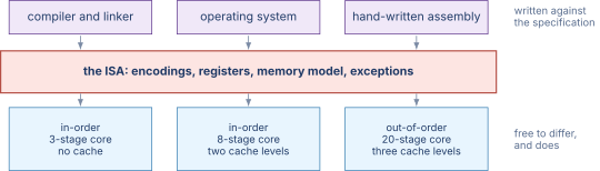
An ISA is not a piece of hardware. It is a specification. Two processors that implement the same ISA can have completely different pipeline depths, cache sizes, and execution unit counts. A program cannot tell the difference as long as every instruction produces the architecturally specified result. This is the meaning of the word contract: the ISA defines what the hardware must do, not how it does it.
The contract has two sides. On the software side, the compiler generates a sequence of binary-encoded instructions that obeys the ISA’s rules. On the hardware side, the processor fetches, decodes, and executes those instructions and produces the results the ISA promises. When the two sides agree, any legal program runs correctly on any compliant implementation. When they disagree, the result is a bug, and the question of who is wrong (the compiler or the chip) is answered by reading the ISA specification.
This separation between specification and implementation is the reason a single ISA can span decades of hardware generations. Intel’s Pentium of 1993 and Intel’s Raptor Lake of 2023 implement the same base x86 ISA. The Pentium has a 5-stage pipeline and a 16 KiB cache. Raptor Lake has a pipeline over 20 stages deep, multiple levels of cache totaling tens of megabytes, and an out-of-order execution engine that can have over 500 instructions in flight at once. Raptor Lake still runs the 32-bit binaries compiled for the Pentium three decades earlier because both honor the same contract.
What the contract deliberately leaves out
The list of what an ISA specifies is the shorter half of the story. The more useful half is what it refuses to specify, because every omission is a degree of freedom handed to the hardware designer, and those degrees of freedom are the subject of most of the rest of this book.
An ISA does not say how many cycles an instruction takes. The RISC-V specification defines what add x1, x2, x3 computes and says nothing about when the result appears. One implementation may produce it in a single cycle, another may take three, and a third may execute it out of order alongside forty other instructions. All three are compliant. This is why a performance claim always names a chip and never an ISA.
An ISA does not say whether a cache exists. Nothing in the ARM A64 specification requires a cache, describes its size, or names its associativity. A load is defined to return the value most recently stored to that address, and how the hardware arranges to make that true is unconstrained. Caches are therefore invisible to a correct single-threaded program, which is exactly the property that lets Chapter 37 change the entire memory system without recompiling anything.
An ISA does not say how deep the pipeline is, how many instructions issue per cycle, or whether the hardware predicts branches. These are the microarchitectural choices that separate a low-power embedded core from a server part running the same binaries.
The line between the two lists is not decorative. When a processor’s behavior depends on something the ISA left unspecified, and software can observe that behavior, the omission has leaked. Timing side channels are precisely this failure: cache occupancy was meant to be invisible, and measuring it turned an implementation detail into an architecturally visible one.
Figure 1 draws the boundary and shows why one interface can carry three unlike machines.
02.Instruction Format and Encoding
Every instruction must be represented as a sequence of bits that the hardware can decode unambiguously. The encoding must answer three questions. First, which operation? Second, where are the operands? Third, where does the result go? The answers are packed into fields within the instruction word. The two major design choices are the width of the instruction word and the layout of those fields.
Fixed-width encoding
A fixed-width encoding uses the same number of bits for every instruction. RISC-V uses 32 bits for all base instructions (the C extension adds 16-bit compressed forms, but those are a separate, optional layer). ARM A64 also uses a uniform 32-bit encoding. Fixed width simplifies the decoder considerably. The hardware knows that every instruction starts exactly 4 bytes after the previous one. Fetching four instructions per cycle means reading a 16-byte aligned block and splitting it into four equal slices. There is no need to scan the byte stream to find instruction boundaries.
The cost of fixed width is encoding pressure. Every instruction, whether it needs one operand or three, whether it carries a 12-bit immediate or none at all, must fit in the same 32 bits. Fields that are unnecessary for a particular instruction type are wasted. RISC-V addresses this by defining six distinct instruction formats (R, I, S, B, U, J), each of which rearranges the 32 bits to suit the instruction class while keeping the opcode and register-specifier fields in consistent positions across formats. Chapter 15 diagrams each format in detail.
Variable-width encoding
A variable-width encoding allows instructions to occupy different numbers of bytes. x86-64 is the canonical example: instructions range from 1 byte (a single-byte NOP) to 15 bytes (a heavily prefixed AVX-512 instruction with a displacement and an immediate). The encoding uses prefix bytes to modify operand size, address size, and vector length, followed by an opcode of one to three bytes, an optional ModR/M byte that encodes the addressing mode, an optional SIB (scale-index-base) byte, an optional displacement of 1, 2, or 4 bytes, and an optional immediate of 1, 2, or 4 bytes (8 bytes for the movabs form of MOV).
The advantage of variable width is density. Simple, common instructions are short. Complex, rare instructions are longer. Code compiled for x86-64 is typically 20 to 30 percent smaller than equivalent RISC-V code because the variable encoding avoids wasting bits on instructions that do not need them.
The cost is decoder complexity. The hardware cannot know where the next instruction starts until it has decoded the current one. Modern x86-64 processors solve this with a dedicated pre-decode stage that scans the byte stream, marks instruction boundaries, and feeds fixed-width internal representations (micro-operations) to the rest of the pipeline. The pre-decode logic consumes meaningful area and power, and it is one of the reasons x86-64 decoders are substantially larger than RISC-V or ARM decoders.
The opcode field
The opcode identifies the operation. In RISC-V, a 7-bit opcode field at bits [6:0] of the 32-bit word selects the major instruction class (load, store, arithmetic, branch, and so on). A secondary funct3 field at bits [14:12] and sometimes a funct7 field at bits [31:25] refine the selection within a class. The three-level hierarchy lets the decoder route instructions quickly: the 7-bit opcode narrows the space to a small family, and the subsidiary fields pick the exact operation.
In ARM A64, a 4-bit field near the top of the word, bits [28:25], identifies the major encoding group, and subsequent bit fields within each group select the specific instruction. The encoding is less regular than RISC-V’s but still fully fixed-width.
In x86-64, the opcode can be 1, 2, or 3 bytes long, preceded by up to four prefix bytes and optionally a REX or VEX or EVEX prefix that extends the register namespace and the vector length. The opcode alone does not uniquely determine the instruction. The ModR/M byte’s reg field sometimes serves as an opcode extension, a practice inherited from the 8086’s need to pack a large instruction set into a single opcode byte.
Immediate encoding
An immediate is a constant encoded within the instruction itself. The width of the immediate field determines the largest constant a single instruction can express. In RISC-V, a standard I-type instruction carries a 12-bit signed immediate, which can represent values from to . The U-type format carries a 20-bit upper immediate, which the LUI instruction places into the upper 20 bits of a register. A two- instruction sequence of LUI followed by ADDI can therefore load any 32-bit constant.
ARM A64 takes a different approach. Many data-processing instructions accept a 12-bit unsigned immediate, optionally shifted left by 12 bits. The MOVZ, MOVK, and MOVN instructions can build an arbitrary 64-bit constant in up to four steps by loading 16 bits at a time. ARM also supports a “bitmask immediate” encoding that represents certain repeating bit patterns in a compact form, covering many constants that would otherwise require multiple instructions.
x86-64 instructions can carry immediates of 8, 16, or 32 bits directly in the instruction stream. A 64-bit immediate is available only for the special MOV to a register (the movabs form). For most instructions, the maximum immediate width is 32 bits, which is sign-extended to 64 bits before use. This means that loading a 64-bit constant that does not fit in 32 sign-extended bits requires either the movabs form or a pair of instructions that load the two halves separately.
Encoding density and code size
The fixed-against-variable argument is usually settled with an appeal to decoder complexity, which is real but hard to feel. Code size is easier to measure, so it is worth measuring.
Take a function that sums an array of thirty-two-bit integers, the four-line loop every introductory course writes. Compiled at -O2, the loop body comes out at roughly forty bytes on RV64GC, thirty-two bytes on AArch64, and twenty-six bytes on x86-64. The ordering is what the encoding widths predict. Variable-width encoding wins on size because a common instruction with small operands can be spent in two or three bytes, where a fixed-width machine pays four for every instruction whether it needs the room or not.
The interesting number is the first one. Plain RV64I, without the compressed extension, would put that same loop at about sixty bytes. The C extension adds sixteen-bit forms of the most frequent instructions and recovers roughly a third of the size, which is why it is present in essentially every RISC-V profile that cares about code footprint. The lesson is that fixed-width is a choice about the decoder, and a fixed-width ISA that wants density back can buy it by admitting a second, shorter instruction length while keeping both lengths trivially distinguishable from the low bits.
Code size is not vanity. Instruction fetch pulls bytes through the same cache hierarchy as data, so a denser encoding puts more of the working set in the same instruction cache, and an instruction cache miss stalls the front end with nothing to hide behind. This is the thread Chapter 37 picks up.
Why the RISC-V immediate is scrambled
Reading the RISC-V specification for the first time, the B-type and J-type immediates look like a mistake. The bits of the branch offset are not laid out in order. Bit 12 sits at the top of the word, bits 10 down to 5 sit in the middle, bits 4 down to 1 sit near the bottom, and bit 11 is stranded on its own between them. Nothing about the number’s value suggests that arrangement.
The arrangement is not about the number. It is about the wires.
Consider what the decoder must build. Every instruction format that carries an immediate has to produce a sign-extended thirty-two-bit value, and the hardware that does this is a set of multiplexers, one per output bit, choosing which instruction-word bit feeds it. The cost of that hardware is the number of distinct sources each output bit can have. If the immediate bits were laid out in the obvious order, each format would place a given immediate bit at a different position in the word, and every output bit would need a wide multiplexer.
The scramble is chosen so that an immediate bit lands in the same instruction-word position across as many formats as possible. Immediate bit 10 comes from word bit 30 in I-type, S-type, B-type and J-type alike. Bit 4 comes from word bit 24 in three of the four. Once the positions agree, the multiplexer for that output bit disappears and becomes a plain wire. Across the whole immediate, the scramble reduces the decode logic to a handful of two-input choices and a sign bit that is always word bit 31.
The sign bit is the clearest case. Every RISC-V immediate is sign-extended from the top bit of the instruction word, in every format, without exception. The sign-extension logic is one wire fanned out to nineteen or twenty bit positions and needs no decoding at all, which matters because sign extension sits on the critical path between fetch and the address adder.
Figure 2 places the same operation from all three families on one bit grid, which is where the field layouts can actually be compared.
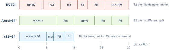
Figure 3 puts the two schemes on the same byte scale, which is where the decoding cost becomes visible.

03.The Register File
The register file is the fastest storage in the processor. A register read takes a fraction of a nanosecond. A cache read takes several nanoseconds. A main-memory read takes tens of nanoseconds. Every ISA defines a set of architectural registers that instructions can name. The number, width, and conventions governing these registers are among the most consequential ISA decisions.
RISC-V registers
RISC-V defines 32 integer registers, each 32 bits wide in RV32 and 64 bits wide in RV64. Register x0 is hardwired to zero. Reading x0 always returns zero, and writing to x0 is silently discarded. This dedicated zero register simplifies many operations. A move from register x5 to register x6, for instance, is encoded as add x6, x5, x0, which adds zero to the source. No separate MOV instruction is needed.
The program counter is not one of the 32 general-purpose registers. It is architecturally visible only through PC-relative addressing and the AUIPC instruction, which adds an upper immediate to the current PC and stores the result in a general-purpose register.
ARM A64 registers
ARM A64 defines 31 general-purpose registers, X0 through X30, each 64 bits wide. The lower 32 bits of each register are accessible as W0 through W30. Register X30 doubles as the link register (the return address for subroutine calls). Unlike RISC-V, ARM A64 does not have a hardwired zero register in the general-purpose file. Instead, a special encoding that would otherwise name a 31st register is interpreted as either the zero register XZR or the stack pointer SP, depending on the instruction. The program counter is not directly accessible as a general- purpose register.
x86-64 registers
x86-64 defines 16 general-purpose registers: RAX, RBX, RCX, RDX, RSI, RDI, RBP, RSP, and R8 through R15. Each is 64 bits wide, with sub-register aliases for the lower 32, 16, and 8 bits (EAX, AX, AL, and so on for each). The original 8086 had only 8 registers. AMD’s x86-64 extension doubled the count to 16 by adding a REX prefix byte that supplies one extra bit per register specifier. Intel’s APX extension, ratified in 2024, doubles the count again to 32 by introducing the REX2 prefix.
The smaller register file of legacy x86-64 puts pressure on the compiler’s register allocator. Spilling a value to the stack because no register is free is more common in x86-64 code than in RISC-V or ARM code, and each spill costs a store followed later by a load. The 16 extra APX registers reduce spilling noticeably for register-hungry workloads.
Why thirty-two, and why not more
Both RISC-V and AArch64 settled on thirty-two integer registers, and the agreement is not coincidence. The number falls out of two pressures pushing in opposite directions.
The pressure downward is encoding space. A register number needs bits, and a three-operand instruction names three of them. At thirty-two registers that is bits of a thirty-two-bit word spent on operand specifiers alone, leaving seventeen for the opcode, the function fields and anything else. Doubling to sixty-four registers costs three more bits, which on a fixed-width machine has to come out of the opcode space or the immediate. RISC-V’s twelve-bit immediate would drop to nine, shrinking the reachable constant range by a factor of eight. That is a steep price.
The pressure upward is spilling. When a function has more live values than registers, the compiler writes one to the stack and reloads it later. Each spill is a store and a load that compute nothing. Measurements on general-purpose integer code have consistently shown the same shape: going from eight registers to sixteen removes a large fraction of spills, sixteen to thirty-two removes most of what is left, and thirty-two to sixty-four removes very little. The curve flattens because the number of simultaneously live values in ordinary code is small. Loops that genuinely need more registers tend to be numerical kernels, and those are served by the vector register file instead.
Thirty-two sits at the knee. It is the smallest count at which spilling stops being a first-order cost, and the largest count that still leaves a workable instruction encoding. x86-64’s sixteen sits below the knee, which is why its compilers spill more and why APX’s extension to thirty-two was worth a new prefix.
There is a third cost that does not appear in the encoding arithmetic and grows faster than either pressure. The register file is a multi-ported memory, and a machine that issues several instructions per cycle needs two read ports and one write port per instruction in flight. Area and access time both grow worse than linearly with the port count, so a register file that is larger and more heavily ported becomes a critical-path problem. Chapter 51 returns to this when the physical register file grows far past the architectural one.
The zero register and its consequences
RISC-V’s x0 reads as zero and discards writes. AArch64 has the same idea in xzr and wzr. Spending one of thirty-two register names on a constant looks wasteful until the instructions it eliminates are counted.
A register-to-register move is an addition of zero, so mv rd, rs is addi rd, rs, 0 and needs no encoding of its own. Negation is a subtraction from zero. A comparison against zero, which is the overwhelmingly common case in loop conditions, is a branch instruction with x0 in one operand slot, so beqz needs no opcode. Loading a small constant is an addition to zero. A no-operation is an addition of zero into zero, which is why the canonical RISC-V nop is addi x0, x0, 0. Discarding a result without suppressing the memory access it depends on is a write to x0.
That is six pseudo-instructions covered by one register convention, and the saving compounds: none of them consume opcode space, and the hardware needs no special cases because reading zero from a register file entry is what it already does.
The cost is one register name out of thirty-two, which the previous subsection showed is on the flat part of the spilling curve. x86-64, which has no zero register and fewer registers to spare, encodes each of these operations separately. Its xor eax, eax idiom for zeroing a register exists because the alternative is spending an immediate.
Figure 4 draws the three files at one scale, which is where the difference in architecturally special registers becomes visible.

Table 1. Architectural register files compared across three ISA families.
| Feature | RISC-V (RV64I) | ARM A64 | x86-64 |
|---|---|---|---|
| Integer registers | 32 (x0 hardwired zero) | 31 + XZR/SP | 16 (32 with APX) |
| Register width | 64 bits | 64 bits | 64 bits |
| Sub-register aliases | No | W0–W30 (32-bit) | EAX, AX, AL, etc. |
| Zero register | x0 | XZR encoding | None |
| Link register | x1 (by convention) | X30 | None (uses stack) |
| Program counter | Not a GPR | Not a GPR | RIP (not a GPR) |
04.Addressing Modes
An addressing mode is a rule for computing the effective address of a memory operand. The number and complexity of addressing modes is one of the sharpest differences between RISC and CISC instruction sets.
Base plus offset
The most common addressing mode across all three families is base plus offset. The instruction names a base register and an immediate offset. The effective address is the sum of the register’s contents and the sign-extended offset. In RISC-V, lw x5, 8(x10) loads a 32-bit word from address . In ARM A64, LDR X5, [X10, #8] does the same. In x86-64, mov eax, [rbx + 8] does the same.
Register indirect
Register indirect is the special case of base plus offset with a zero offset. RISC-V writes it as lw x5, 0(x10). ARM writes LDR X5, [X10]. The assembler syntax differs, but the hardware behavior is identical: the effective address is the contents of the base register.
PC-relative addressing
PC-relative addressing computes the effective address as the program counter plus a signed offset. All three ISAs use it for branch targets. RISC-V also uses it for data access through the AUIPC + LW two-instruction idiom, which is how position- independent code loads global variables. ARM A64 provides a dedicated ADRP instruction that forms a 4 KiB-aligned PC-relative address, paired with a subsequent load that adds the page offset. x86-64 introduced RIP-relative addressing in the 64-bit extension, making PC-relative data access a single instruction.
Scaled index (x86-64)
x86-64 supports a scaled index mode in which the effective address is , where the scale is 1, 2, 4, or 8. This mode is encoded through the SIB byte. It maps directly to array element access when the element size is a power of two: mov eax, [rbx + rcx*4] loads the rcx-th 4-byte element of an array whose base is in rbx. RISC-V has no single-instruction equivalent and requires a shift followed by an add to compute the same address. ARM A64 offers a shifted-register offset mode (LDR X5, [X10, X11, LSL #2]) that covers most of the same cases in one instruction, though it lacks x86-64’s independent displacement.
Pre-index and post-index (ARM A64)
ARM A64 supports pre-index and post-index modes that update the base register as a side effect of the load or store. In pre-index mode, the base is updated before the access: LDR X5, [X10, #8]! adds 8 to X10, then loads from the new address. In post-index mode, the base is updated after the access: LDR X5, [X10], #8 loads from the original X10, then adds 8 to X10. These modes are useful for walking through arrays and for stack operations. RISC-V deliberately omits them to keep the microarchitecture simpler (a load that also writes back to the base register requires two write ports to the register file in a single cycle).
What an addressing mode costs in the datapath
Addressing modes are usually presented as a menu of conveniences for the programmer. Read that way, more is better and RISC-V’s single mode looks impoverished. The menu framing hides the cost, because every mode has to be built out of hardware that sits between the register file and the data cache, on a path that is frequently the one setting the clock period.
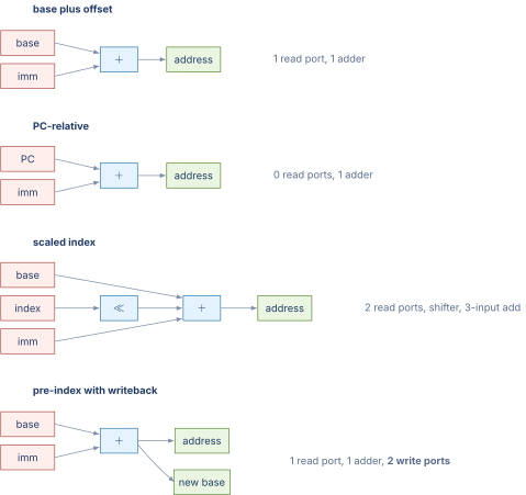
Work through what each mode needs. Base plus offset reads one register, sign-extends an immediate, and adds them. That is one register read port and one adder. Register indirect is the same with the offset forced to zero, so it costs nothing extra. PC-relative addressing swaps the register read for the program counter, which is already available in the fetch stage, so it again needs one adder and no new port.
Scaled index is where the arithmetic changes. Computing [rbx + rcx*4 + 8] reads two registers, shifts one of them by a variable amount, and sums three terms. That is two read ports, a shifter, and a three-input addition. The shifter is cheap because the scale is limited to four values and reduces to a small multiplexer, but the second read port is not, and the three-input add is a wider carry structure than the two-input one. On a machine issuing several memory operations per cycle, each additional port multiplies through the whole register file.
Pre-index and post-index cost something different again, and it is the cost the earlier subsection named. The address computation itself is ordinary base plus offset. The expense is the writeback of the updated base, which turns a load into an instruction with two destination registers. A register file sized for one write per instruction now needs two, or the machine must split the instruction internally into two operations, which is what several AArch64 implementations do.
This is the argument behind RISC-V’s single mode, and it is not an argument that addressing modes are useless. It is an argument about where the complexity is paid. A scaled-index load in x86-64 is one instruction that the hardware must be built wide enough to execute; the same computation in RISC-V is a shift, an add and a load, three instructions that the compiler emits and that a machine with three-wide issue retires in roughly the same time. The instruction count is worse and the hardware is simpler. Which trade wins depends on whether the front end or the execution core is the constraint, and Chapter 49 takes up that question with numbers.
Figure 5 draws the address computation for each mode as the datapath fragment it implies.
05.Condition Codes and Predication
When a program must branch based on the result of a comparison, the ISA must provide a mechanism for testing that result. Two fundamentally different approaches exist, and the three ISA families in this book illustrate both.
Condition codes in ARM A64 and x86-64
ARM A64 and x86-64 both use condition codes: a small set of single-bit flags that arithmetic instructions update as a side effect of computing their result. The four standard flags are N (negative), Z (zero), C (carry), and V (overflow). A conditional branch tests a Boolean combination of these flags. For example, B.EQ label in ARM A64 branches if the Z flag is set, which happens when the most recent flag-setting instruction produced a zero result.
In x86-64, nearly every arithmetic and logical instruction updates the flags register (EFLAGS). In ARM A64, most data-processing instructions update the flags only when the S suffix is present (ADDS, SUBS), giving the programmer control over when flags change. This distinction matters for out-of-order execution: when every instruction updates flags, the flag register becomes a bottleneck because later instructions that read flags must wait for earlier instructions that write them. ARM’s selective flag update reduces that pressure.
Comparison and branch in RISC-V
RISC-V takes a different path. It has no condition-code register. Instead, conditional branches compare two registers directly. The instruction beq x5, x6, label branches if registers x5 and x6 are equal. The comparison and the branch happen in the same instruction. There is no separate compare step and no shared flag register. This eliminates the flag-register bottleneck entirely and simplifies the out-of-order rename logic, because there is no implicit output register that every arithmetic instruction writes.
The trade-off is that RISC-V cannot express “branch if the previous addition overflowed” in a single instruction. Detecting overflow requires an explicit sequence: perform the addition, then use a comparison instruction to check whether the result is smaller than one of the operands (for unsigned overflow) or whether the sign of the result is inconsistent with the signs of the operands (for signed overflow). In practice this is a rare code pattern, and the RISC-V designers judged that avoiding the flag register was worth the occasional extra instruction.
Why RISC-V has no flags register
Condition codes are convenient and nearly universal. ARM has NZCV, x86-64 has RFLAGS, and both have carried a flags register since their first generation. RISC-V has none, and folding the comparison into the branch is the visible consequence. The reason is not minimalism for its own sake. A flags register is a single architectural location that almost every arithmetic instruction writes and every conditional branch reads, and that shape becomes expensive exactly when a machine tries to go wide.
Consider what an out-of-order processor must do with it. Register renaming, which Chapter 51 develops in full, works by giving each write to an architectural register a fresh physical location, so that two instructions writing the same name do not have to execute in order. Flags need the same treatment, because otherwise every arithmetic instruction is serialized against every other one through NZCV. So the flags register gets renamed too.
The trouble is that flags are not one value. NZCV is four bits that different instructions write in different combinations: an addition writes all four, a logical operation writes two and leaves the carry alone, and a compare writes all four from a subtraction whose result is discarded. An instruction that writes some flags and preserves others has to read the previous value to reconstruct the rest, which turns a write into a read-modify-write and creates a dependence on the most recent prior flag writer. Implementations answer this by splitting the flags into separately renamed groups, which is more rename bandwidth and more comparison logic on a structure consulted by every branch.
RISC-V avoids the structure entirely. blt x1, x2, label reads two ordinary registers and writes none, so it participates in exactly the same renaming machinery as everything else and adds no special case. The cost is that a comparison whose result is used more than once must be recomputed or materialized into a register with slt, which is an extra instruction in code that branches twice on the same condition.
06.The Exception Model
Not every instruction completes normally. A division by zero, an access to an unmapped address, a page fault, a timer interrupt, or a debug breakpoint all divert the processor from the normal fetch-decode-execute sequence. The ISA must specify precisely what happens in each case: which register saves the faulting address, where the handler starts, what state the handler can inspect, and how the handler returns to normal execution.
Synchronous exceptions and asynchronous interrupts
An exception can be synchronous or asynchronous. A synchronous exception, also called a trap or fault, is caused by the execution of a specific instruction. Division by zero is synchronous: the exception is tied to the DIV instruction that attempted the division. A page fault is synchronous: the exception is tied to the load or store that accessed the unmapped page.
An interrupt is asynchronous. It is caused by an external event (a timer, a disk controller, a network interface) that has nothing to do with the currently executing instruction. The processor checks for pending interrupts between instructions and diverts to the handler when one is found.
Exception handling in RISC-V
RISC-V defines a set of control and status registers (CSRs) that manage exceptions. When an exception occurs in machine mode, the processor writes the address of the faulting or interrupted instruction to mepc, writes a cause code to mcause, and jumps to the address stored in mtvec. The handler inspects mcause to determine the exception type, handles it, and executes MRET to return to the interrupted instruction. The privileged specification defines analogous registers for supervisor mode (sepc, scause, stvec) and, optionally, for hypervisor mode.
Exception handling in ARM A64
ARM A64 uses four exception levels, EL0 through EL3, with EL0 being the least privileged (user applications) and EL3 being the most privileged (secure monitor firmware). When an exception occurs, the processor saves the return address in ELR_ELn (Exception Link Register) and the saved processor state in SPSR_ELn (Saved Program Status Register), then jumps to the vector table base address stored in VBAR_ELn plus an offset that depends on the exception type and the originating exception level. The handler executes ERET to return.
Exception handling in x86-64
x86-64 uses a different mechanism rooted in the 8086’s interrupt descriptor table. When an exception or interrupt fires, the processor looks up the handler address in the Interrupt Descriptor Table (IDT), pushes the return address and flags onto the kernel stack, and jumps to the handler. The IRET instruction pops the saved state and returns. Protection levels (rings 0 through 3, though modern operating systems use only ring 0 for the kernel and ring 3 for user space) govern which code can execute which instructions and access which memory regions.
Table 2. Exception model comparison across three ISA families.
| Feature | RISC-V | ARM A64 | x86-64 |
|---|---|---|---|
| Privilege levels | M, S, U (+ optional H) | EL0–EL3 | Ring 0–3 (2 used) |
| Saved PC register | mepc / sepc | ELR_ELn | Pushed to stack |
| Cause register | mcause / scause | ESR_ELn | Error code on stack |
| Vector table | mtvec / stvec | VBAR_ELn | IDT |
| Return instruction | MRET / SRET | ERET | IRET |
Precise exceptions and why they are hard
Everything above assumed that when an exception is taken, the machine is in a clean state: every instruction before the faulting one has completed, the faulting one and everything after it has had no effect, and the saved program counter names exactly where to resume. That property has a name. An exception is precise when the architectural state the handler observes is the state that would have existed if the program had been executed one instruction at a time up to the faulting instruction and then stopped.
Precision is not a convenience. Demand paging depends on it. When a load touches a page that is not resident, the handler fetches the page and returns, and the load re-executes. That only works if the load had no effect the first time and nothing after it did either. Debuggers depend on it, because a breakpoint that reported an ambiguous position would be useless. So does any language with exceptions or signals.
The difficulty is that no high-performance processor executes one instruction at a time. Instructions issue several per cycle, execute out of order, and finish in whatever order their operands and functional units allow. A divide issued early may still be running when a dozen later instructions have already produced results. If the divide then raises a divide-by-zero, the machine must present a state in which none of those later instructions ever happened, even though their results already exist somewhere in the hardware.
The resolution is to separate the point at which an instruction computes its result from the point at which that result becomes architecturally visible. Instructions execute whenever they can, in any order, and their results are held in a structure that is not the architectural state. They are then committed strictly in program order, and an instruction is allowed to commit only when every instruction before it has committed and it is known not to fault. When a fault is discovered, everything not yet committed is discarded, which costs the work but preserves the illusion.
That structure is the reorder buffer, and Chapter 52 builds it. What matters here is that precision is an architectural requirement stated by the ISA and a microarchitectural burden paid by the implementation. It is the clearest example in this chapter of the contract constraining hardware without describing it: the specification says the handler must see a coherent state, says nothing about reorder buffers, and thereby makes them necessary.
07.Memory Ordering
When a program runs on a single core, loads and stores appear to execute in the order the program specifies. When two or more cores share memory, the question of ordering becomes subtle. If core A writes a value and then writes a flag, does core B necessarily see the value before the flag? The ISA’s memory ordering model answers this question.
Sequential consistency
The strongest model is sequential consistency, defined by Leslie Lamport in 1979. Under sequential consistency, the result of any execution is the same as if the operations of all cores were interleaved in some total order, and the operations of each core appear in the order specified by the program. This is the model that matches the programmer’s natural intuition. It is also the most expensive to implement, because the hardware cannot reorder any memory access past any other.
Total store ordering (TSO)
x86-64 implements total store ordering (TSO). Under TSO, each core sees its own stores in program order, and stores from all cores appear in a single total order that every core agrees on. Loads, however, may be reordered ahead of earlier stores to different addresses. The practical consequence is that a store-then-load sequence to different addresses may appear reordered to another core. The MFENCE instruction or a locked instruction (LOCK XCHG, LOCK CMPXCHG) enforces sequential ordering when the program needs it.
TSO is close enough to sequential consistency that most programmers never notice the difference. The one case that matters is the classic store buffer forwarding pattern, where core A writes x = 1 then reads y, and core B writes y = 1 then reads x. Under TSO, both cores can read zero, because each core’s load can bypass its own pending store. Under sequential consistency, at least one core must see the other’s store.
Relaxed ordering
ARM A64 and RISC-V both specify a relaxed base memory model in which the hardware is free to reorder loads and stores in almost any way, as long as single-core program order is maintained from that core’s own perspective. The programmer must insert explicit fence instructions (FENCE in RISC-V, DMB in ARM A64) to enforce ordering between specific pairs of accesses. This places a greater burden on the programmer and the compiler but gives the hardware more freedom to reorder memory operations for performance.
RISC-V also provides acquire and release annotations on atomic instructions (the A extension). A load-acquire prevents subsequent loads and stores from moving before it. A store-release prevents earlier loads and stores from moving after it. Together, acquire and release form a one-directional fence that is cheaper than a full bidirectional fence.
One litmus test read three ways
The three models above are easier to believe than to apply. The standard way to pin down what a memory model actually permits is a litmus test: a very short program, run on two cores, whose final register values reveal which reorderings the hardware allowed. One test separates all three models, and it is worth working through completely.
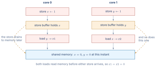
Both memory locations start at zero. Core 0 stores 1 to and then loads into r1. Core 1 stores 1 to and then loads into r2. Neither core’s two instructions touch the same address, so nothing forces an ordering within a core except the memory model.
Ask whether both loads can return zero.
Under sequential consistency, they cannot. Sequential consistency requires that some single interleaving of the four instructions explains the result, with each core’s instructions in program order. If r1 is zero, core 0’s load ran before core 1’s store, and since core 0’s store precedes its own load, core 0’s store ran before core 1’s store. Symmetrically, if r2 is zero then core 1’s store ran before core 0’s. Both cannot hold, so is impossible.
Under total store ordering, they can, and the reason is the store buffer. A store retires into a per-core buffer and drains to memory later, while loads are allowed to proceed past buffered stores to other addresses. So core 0’s store to can still be sitting in core 0’s buffer when core 0’s load of executes, and the same on core 1. Both loads read memory that neither store has reached, and both return zero. This is not a hardware defect. It is the one reordering TSO permits, and x86-64 permits it.
Under a relaxed model such as RVWMO or the AArch64 model, they can also both be zero, and for more reasons. Store-to-load reordering is permitted as in TSO, and so is reordering the two independent instructions within a core outright, since nothing in the program establishes a dependence between them.
The practical consequence is the same in the second and third cases and it is what the fence instructions are for. Making the outcome impossible requires a fence between the store and the load on both cores, and it must be on both: fencing one core still permits the other to reorder and produce the result. In C or C++ the same effect comes from making both variables atomic and leaving the default sequentially consistent ordering in place, which the compiler lowers to the right fence for each target.
Figure 6 draws the test as a time diagram with the store buffers made visible, since the buffers are where the counter-intuitive outcome comes from.
08.Calling Conventions
The ISA defines the registers. The calling convention defines how independently compiled functions use them. Without a shared convention, a caller cannot know which registers the callee will preserve and which it will overwrite. The convention is not part of the ISA specification itself. It is part of the application binary interface (ABI), which sits one layer above the ISA and is enforced by the compiler and the operating system.
Caller-saved and callee-saved registers
The convention divides registers into two classes. Caller-saved (also called volatile) registers are not preserved across a function call. If the caller needs the value after the call returns, it must save the register to the stack before the call and restore it afterward. Callee-saved (also called non-volatile) registers are preserved: the callee must save them at function entry and restore them at function exit if it intends to use them.
In RISC-V, registers x5–x7 and x10–x17 (the t and a registers in the standard ABI naming) are caller-saved. Registers x8–x9 and x18–x27 (the s registers) are callee-saved. In ARM A64, X0–X18 are caller-saved (with X18 reserved on some platforms), and X19–X28 are callee-saved. In x86-64 under the System V ABI, RBX, RBP, and R12–R15 are callee-saved, and the remaining registers are caller-saved.
Argument passing
All three conventions pass the first several arguments in registers. RISC-V uses a0–a7 (up to 8 arguments). ARM A64 uses X0–X7 (up to 8). x86-64 under the System V ABI uses RDI, RSI, RDX, RCX, R8, and R9 (up to 6 integer arguments). Arguments beyond the register limit are passed on the stack. The return value goes in a0 (RISC-V), X0 (ARM), or RAX (x86-64).
The stack frame
When a function needs local storage beyond what registers provide, it allocates space on the stack. The stack grows downward in all three ISAs. The calling convention specifies the alignment of the stack pointer (16 bytes in all three) and the layout of the saved registers, the return address, and the local variables within the stack frame. A consistent layout makes it possible for debuggers, profilers, and exception unwinders to walk the chain of stack frames and reconstruct the call sequence at any point during execution.
Where the four ABIs disagree
The three ISAs in this chapter carry four calling conventions between them, because x86-64 has two. The System V AMD64 ABI is used by Linux, the BSDs and macOS, and the Microsoft x64 calling convention is used by Windows. They disagree on nearly every choice, which is why a function pointer cannot be passed between code compiled for the two without a thunk, and why cross-platform assembly is written twice.
The disagreements are worth tabulating, because each one is a design decision with a visible cost, not an arbitrary difference.
Table 3. The four calling conventions compared. Each row is a choice with a cost, not a convention picked at random.
| RISC-V | AArch64 | System V | Microsoft | |
| (LP64) | (PCS) | AMD64 | x64 | |
| Integer arg registers | 8 (a0–a7) | 8 (X0–X7) | 6 | 4 |
| Float arg registers | 8 (fa0–fa7) | 8 (V0–V7) | 8 | 4 |
| Return value | a0, a1 | X0, X1 | RAX, RDX | RAX |
| Return address | ra (x1) | X30 (LR) | on stack | on stack |
| Stack alignment at call | 16 bytes | 16 bytes | 16 bytes | 16 bytes |
| Caller-allocated spill | none | none | none | 32 bytes |
| Stack cleanup | caller | caller | caller | caller |
| Variadic float handling | in integer regs | on stack | AL holds count | shadowed in both |
Three rows deserve comment.
The argument-register count is the clearest divergence, and it follows directly from how many registers each machine has. RISC-V and AArch64 can afford eight because they have thirty-two. System V passes six out of sixteen, and Microsoft x64 passes four, leaving more registers callee-saved. Fewer argument registers means more calls spill to the stack, and a call with seven arguments costs three stores under Microsoft x64 and none under either RISC-V or AArch64.
The shadow space is unique to Microsoft x64 and often surprises people reading disassembly for the first time. The caller must allocate thirty-two bytes on the stack immediately above the return address, whether or not the callee uses them, giving the callee somewhere to spill its four register arguments without adjusting the stack pointer. It costs a small amount of stack on every call and simplifies the callee’s prologue and any code that needs to take the address of an argument.
Variadic functions are where the conventions differ most and where the cost is highest. System V AMD64 requires the caller to place the number of vector registers used into AL before calling a variadic function, so that va_start knows how much register state to save. That is why calling printf from hand-written assembly with a forgotten xor eax, eax produces a crash rather than wrong output. RISC-V takes the simpler route of passing floating-point variadic arguments in integer registers, which costs a move at the call site and removes the special case entirely.
09.Putting It Together: The ISA Checklist
Every ISA, together with the ABI built on top of it, must answer the same set of questions. The answers differ across RISC-V, ARM A64, and x86-64, but the questions are universal.
-
Instruction encoding. Fixed or variable width? How many bits? How is the opcode distinguished from operands?
-
Register file. How many registers? How wide? Is there a hardwired zero register? A dedicated link register?
-
Addressing modes. Which modes are supported? Base plus offset? Scaled index? Pre/post-index?
-
Data types. Which integer and floating-point widths does the hardware operate on natively?
-
Control flow. Condition codes or direct comparison? How are branches, jumps, and calls encoded?
-
Exception model. How are faults and interrupts vectored? What state is saved? How does the handler return?
-
Memory ordering. Sequential consistency, TSO, or relaxed? What fence instructions are available?
-
Calling convention (ABI layer). How are arguments passed? Which registers are preserved? How does the stack grow?
The next four chapters examine these ISAs through this lens. Chapter 14 places the ISAs in historical context by tracing the RISC-versus-CISC debate. Chapter 15 dissects RISC-V in detail. Chapter 16 does the same for ARM A64. Chapter 17 does the same for x86-64.
10.Worked Examples
11.Exercises
References
- [1]Waterman, Andrew and Asanovi\'c (2024). “The RISC-V.”
- [2]Waterman, Andrew and Asanovi\'c (2024). “The RISC-V.”
- [3](2024). “ARM.”
- [4](2024). “Intel.”
- [5](2024). “AMD64.”